Slip Ring Buying Guide for OEM Engineers: Types, Specs & Supplier Checklist
Key Takeaways:
Beyond Basic Circuit Counts: Specifying a slip ring requires evaluating continuous/peak current, dynamic contact resistance, signal shielding, mechanical envelope, and environmental protection (IP54 to IP69K).
Match Structure to Machinery: Choose through-bore for shaft clearance, pancake for axial constraints, high-current for power transmission, or hybrid rotary unions for combined electrical, data, and fluid transfer.
Define Testing and Verification Upfront: Insist on dynamic contact resistance measurement under rotation, dielectric strength tests (1000V+ AC), vibration/shock profiling, and salt-spray validation.
Prepare Complete RFQs: Detailed upfront RFQs with precise electrical loads, environmental conditions, duty cycles, and mounting constraints prevent costly engineering redesigns and field failures.
Introduction
This slip ring buying guide is designed for OEM engineers, equipment designers, maintenance engineers, technical buyers, and procurement teams responsible for specifying electrical and rotary transmission assemblies in industrial equipment.
Selecting an electromechanical slip ring involves far more than simply selecting the number of electrical circuits or picking a nominal current rating from a component catalog. A slip ring operates as a critical rotational junction: it must maintain continuous electrical contact across moving interfaces while enduring mechanical vibration, thermal cycling, environmental contaminants, and continuous duty cycles.
This guide provides an end-to-end framework covering every major buying factor: slip ring structural types, key electrical specifications, signal integrity and EMC guidelines, mechanical integration constraints, IP protection ratings, rigorous verification testing, standard vs. custom design trade-offs, total cost of ownership (TCO), and supplier evaluation criteria.
By using this guide, OEM engineering and procurement teams can systematically prepare comprehensive technical specifications and Request for Quotation (RFQ) packages that eliminate engineering communication delays, prevent field failures, and ensure long-term equipment reliability.
When Do You Need a Slip Ring?
Typical OEM Applications
Industrial machinery frequently requires transferring electrical power, control commands, digital feedback signals, or fluid media between a stationary structure and a continuously rotating assembly. Slip rings are essential components across a wide spectrum of OEM industries:
Construction Machinery: Excavators, mobile rotary cranes, concrete boom pumps, and pile-driving equipment requiring 360-degree continuous turret or boom rotation.
Cranes and Lifting Equipment: Port container cranes, offshore pedestal cranes, rubber-tired gantry (RTG) cranes, and overhead crane cable reels.
Excavators and Drilling Equipment: Rotary mining drills, horizontal directional drilling (HDD) rigs, and tunnel boring machines (TBMs).
Offshore and Marine Equipment: Winch drums, offshore crane swivels, azimuth thrusters, pipe-laying reels, and remotely operated vehicle (ROV) tether handling systems.
Industrial Automation: Rotary index tables, automated packaging machinery, filling machines, wrapping equipment, and indexing carousels.
Robotics: Articulated robot joints, hollow-bore robotic wrist actuators, and gantry pick-and-place rotating heads.
Rotating Platforms and Turntables: Stage lighting turntables, industrial inspection carousels, and amusement park rides.
Cable Reels and Winches: Motorized spring reels, hose reels, and tether recovery systems.
Power, Signal, Data, and Fluid Transfer Requirements
Modern OEM machinery rarely relies on simple single-purpose rotary electrical joints. Equipment designs increasingly demand multi-passage hybrid transmission across rotating interfaces:
Continuous Electrical Power Transmission: Delivering high continuous current to drive electric motors, hydraulic pumps, heating elements, or auxiliary battery charging systems.
Analog and Digital Signal Transmission: Transmitting low-voltage sensor feedback, thermistor readings, encoder pulses, limit switch signals, and 4-20mA current loops without electrical noise distortion.
Industrial Communication Protocols: Transmitting high-speed bus data including CAN Bus, Profibus, EtherCAT, PROFINET, and industrial Ethernet (100 Mbps to 1 Gbps) with strict impedance matching and minimal packet loss.
Fiber-Optic Transmission: Routing high-bandwidth optical channels (single-mode or multi-mode) using Fiber Optic Rotary Joints (FORJ) to eliminate electromagnetic interference (EMI) over long distances.
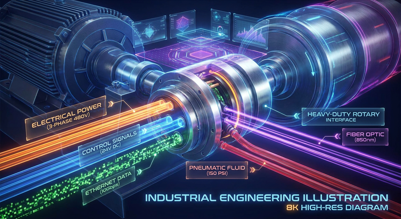
Pneumatic or Hydraulic Media in Hybrid Rotary Systems: Integrating fluid swivels to transfer compressed air, coolant, or high-pressure hydraulic oil alongside electrical circuits within a unified housing envelope.
When a Cable Loop or Standard Connector Is Not Enough
In early machine prototyping, designers sometimes attempt to route electrical wiring using flexible cable loops or coiled harnesses. However, hard-wired cable loops fail rapidly under specific operational constraints:
Continuous 360-Degree Rotation: Cable loops physically twist and break when rotation is unbounded or continuous in one direction.
Frequent Rotational Movement: High duty cycles cause severe flexural fatigue, insulation abrasion, and wire strand breakage.
Limited Installation Space: Coiled cable loops require large physical swept volumes, which are incompatible with compact equipment envelopes.
High-Current Transmission: Heavy-gauge power cables cannot endure repeated torsional flexing without fatigue failure.
Multiple Signal Types: Combining power lines, high-speed data cables, and hydraulic hoses in a loose bundle causes severe signal crosstalk and mechanical entanglement.
Harsh Operating Environments: Outdoor exposure to dirt, moisture, UV radiation, and mechanical abrasion degrades exposed wiring harnesses rapidly.
When any of these conditions exist, specifying a dedicated slip ring assembly or hybrid rotary union is mandatory to ensure machinery safety and operational continuity.
Choosing the Right Slip Ring Type
Selecting the correct structural architecture is the first step in slip ring integration. Mechanical envelope, bore requirements, mounting interfaces, and signal types determine which slip ring design is most appropriate.
Through-Bore Slip Rings
Through-bore (or hollow-shaft) slip rings feature a central hollow aperture designed to accommodate a rotating drive shaft, hydraulic pipe, pneumatic conduit, or internal wiring harness.
Suitable Applications: Excavator center swivels, heavy machinery turntables, wind turbines, cable reels, and automated packaging equipment.
Key Considerations: Bore diameter (ranging from 12 mm to over 500 mm), outer diameter constraints, current capacity per ring, and stator/rotor torque arm mounting methods.
Flange and Integrated Slip Rings
Flange-mounted slip rings incorporate standard mounting flanges on the rotor or stator housing, simplifying direct mechanical installation into equipment bulkheads, gearboxes, or structural frames.
Suitable Applications: Industrial turntables, crane cable drums, rotary index tables, and robot bases.
Key Considerations: Flange pitch circle diameter (PCD), bolt circle tolerances, axial depth clearance, radial alignment tolerance, and resistance to structural vibration.
Pancake Slip Rings
Pancake (or flat) slip rings arrange conductive channels concentrically on a flat, disc-like plane rather than along a cylindrical shaft.
Suitable Applications: Space-constrained equipment where axial length is severely restricted but radial space is available.
Trade-offs: Pancake designs offer ultra-short axial length, but require larger outer diameters, exhibit higher ring-to-ring sliding velocity differential, experience faster brush wear on outer tracks, and present lower thermal dissipation capacity compared to cylindrical designs.
Capsule and Compact Slip Rings
Capsule slip rings consolidate gold-on-gold contact technology into a small, fully enclosed housing, offering high channel density in compact physical dimensions.
Suitable Applications: Surveillance gantry cameras, small robotics, medical devices, test instruments, and low-current automation.
Limitations: Capsule designs are optimized for low current (typically 2A to 5A per circuit) and signal-level voltages; they are generally not suitable for heavy-duty industrial power or high-impact construction environments. Technical specifications for compact units can be reviewed in the Jinpat Slip Ring Technical Overview.
High-Current Slip Rings
High-current slip rings are engineered specifically for transmitting heavy electrical power loads safely across rotating interfaces.
Suitable Applications: Construction cranes, mining excavators, offshore winches, ship propulsion thrusters, and heavy industrial welding platforms.
Key Considerations: Continuous current rating (from 50A to 1,500A+ per circuit), busbar/conductor sizing, thermal dissipation design, insulation clearance distance, temperature rise thresholds, and high startup current duty cycles.
Hybrid Slip Rings
Hybrid slip rings integrate multiple media transmission types within a single compact rotary assembly.
Combined Transmission: Electrical power, low-level signals, industrial Ethernet, fiber optics (FORJ), and pneumatic or hydraulic rotary passages.
OEM Benefits: Eliminates duplicate rotary components, reduces equipment assembly labor, optimizes space envelopes, and simplifies overall machine Bill of Materials (BOM).
Ethernet, CAN Bus, and High-Speed Data Slip Rings
High-speed data slip rings are specifically engineered to preserve signal integrity and transmission quality for digital communication protocols under continuous movement.
Key Design Factors: Controlled characteristic impedance (100 Ω for Ethernet, 120 Ω for CAN Bus), 360-degree continuous shielding, internal physical separation between power and signal channels, grounding isolation, and specialized low-attenuation connectors.
Fiber Optic Rotary Joints and Electro-Optical Hybrid Solutions
Fiber Optic Rotary Joints (FORJ) utilize optical signals to transfer ultra-high bandwidth data across rotating joints without electrical contacts.
Suitable Applications: Long-distance video transmission, radar antennas, offshore umbilical reels, defense systems, and high-EMI industrial environments.
OEM Benefits: Immune to electromagnetic interference, offers gigabit-plus bandwidth, zero contact wear, and spark-free operation in explosive environments.

Key Electrical Specifications to Define Before Buying
Accurate electrical specification is vital to prevent overheating, electrical noise, signal distortion, and premature insulation breakdown.
Number of Circuits
Total Channel Count: Define the exact number of independent electrical paths required.
Circuit Separation: Strictly separate high-power circuits, AC control lines, DC control lines, analog sensor lines, and high-speed data lines.
Spare Circuits: Include 10% to 20% spare channels to accommodate future machinery feature upgrades or field sensor additions.
Current Per Circuit
Individual Circuit Ratings: Specify the continuous operational current required for each individual circuit.
Avoid Average Division: Total equipment current should never simply be divided equally across all circuits. A slip ring carrying a 100A main drive line and ten 2A sensor lines requires specific conductor sizing for each track.
Current Profiles: Clearly distinguish continuous current, peak transient current, motor startup inrush current, and duty cycle duration.
Voltage
Operating Voltage: Specify AC or DC operating voltage for each circuit group (e.g., 24 VDC, 240 VAC, 480 VAC, 690 VAC, or up to 6,000 VAC for high-voltage mining machinery).
Insulation Safety Margin: Ensure proper dielectric spacing and insulation resistance. High-voltage power channels require elevated creepage and clearance distances to prevent arc tracking.
Power and Temperature Rise
Electromechanical slip rings generate internal heat due to contact resistance between sliding brushes and conductive rings, as well as resistive heating in internal conductors.
Factors Influencing Temperature Rise: Operating current, brush contact resistance, total circuit density, enclosure thermal conductivity, ambient operating temperature, and duty cycle.
Thermal Thresholds: Ensure total internal temperature (ambient plus operational rise) does not exceed brush wire plating and insulation material limits (typically kept under +85°C for standard models, or +150°C+ for high-temperature custom designs).
Signal and Data Requirements
Specify exact signal protocols to ensure appropriate contact materials and internal shielding are selected:
Analog Signals: 4-20mA instrumentation loops, 0-10V control signals, thermocouple outputs, and RTD temperature sensors.
Digital Signals: 24V PLC I/O, optical encoder pulses, proximity sensors, and limit switches.
Bus & Data Protocols: CAN Bus (ISO 11898), Ethernet (100BASE-TX / 1000BASE-T), RS-485, RS-422, Profibus, HD-SDI video, and fiber optics.
Signal Integrity and EMC
To prevent electrical noise interference on sensitive data channels in machinery with heavy motors and drives:
Shielding: Individual channel shielding and overall braided outer shielding.
Grounding: Dedicated low-impedance ground paths and housing bonding.
Crosstalk & Noise: Target dynamic contact resistance variation of less than 10 mΩ to prevent signal jitter. High-performance industrial standards can be referenced in the Jinpat Industrial Slip Ring Specification Standards.
Physical Separation: Isolate high-power conductors from sensitive data wires by using internal metallic shielding barriers or spatial physical offset.
Mechanical Integration Requirements
Mechanical fit, mounting alignment, rotational speed, and cable exit geometry directly impact installation efficiency and mechanical operating life.
Rotational Speed
RPM Parameters: Define normal continuous operating RPM, intermittent peak RPM, and maximum allowable overspeed.
Speed Effects: Rotational speed drives sliding velocity at the brush-ring interface. Higher RPM increases frictional heat, accelerates mechanical wear, increases dynamic contact noise, and reduces service life.
Duty Cycle
Continuous Rotation: Machinery operating 24/7 at constant speed (e.g., rotary pumps, packaging carousels).
Intermittent Rotation: Periodic movement triggered by machine cycles (e.g., crane slewing, indexing tables).
Oscillating Movement: Partial back-and-forth rotation (e.g., ±180 degree robotic wrist rotation), which can concentrate wear on localized ring segments if improper contact alloys are selected.
Start-Stop Cycles: Frequent high-acceleration starts and stops requiring low rotational inertia and robust drive torque pins.
Installation Space
Define strict physical envelope limits during the concept design stage:
Outer Diameter (OD): Maximum allowable external housing clearance.
Overall Length (L): Maximum axial dimension including cable glands and strain relief.
Through-Hole Diameter: Internal clearance required for drive shafts or fluid conduits.
Radial & Axial Constraints: Ensure adequate clearance for assembly tool access and maintenance.
Mounting Method
Flange Mounting: Flange bolted to machine frame, rotor driven by shaft pin or flexible drive arm.
Shaft Mounting: Slip ring rotor secured directly to driven shaft via setscrews or locking collar.
Rotor/Stator Orientation: Clarify which section rotates (rotor) and which remains fixed (stator).
Flexible Torque Arm Rule: Never rigidly clamp both the rotor and stator simultaneously. One side must be restrained using a flexible torque arm or anti-rotation pin to absorb structural misalignment and thermal expansion without overloading internal bearings.
Cable Routing and Connector Requirements
Cable Specifications: Conductor gauge (AWG), insulation material (Teflon, PVC, PUR), shielding type, and jacket flexibility.
Cable Exit Directions: Radial exit, axial exit, or custom angled exit fittings.
Connectors: Military-spec circular connectors (e.g., MIL-DTL-38999), industrial heavy-duty rectangular connectors, or Flying Leads with specified wire lengths.
Strain Relief: Integrated heavy-duty cable glands, strain relief clamps, or protective conduit fittings to prevent mechanical tension on internal brush solder joints.
Expected Service Life
Target Service Horizon: Define required operational lifespan in total revolutions (e.g., 50 million to 100+ million revolutions) or operating hours (e.g., 20,000 to 50,000 service hours).
Upfront Specification: Service life expectations dictate brush contact metallurgy (e.g., precious metal gold-gold vs. silver-graphite), bearing quality, lubrication type, and maintenance access design.
Environmental and Protection Requirements
Environmental factors are primary drivers of premature field failures. Ingress of moisture, dust, chemical vapors, or corrosive salt spray rapidly compromises electrical insulation and brush contact stability.
IP Protection Rating
The Ingress Protection (IP) rating according to IEC 60529 must match the machine's operational environment:
IP50 / IP54: Suitable for enclosed indoor automation machinery with basic dust protection.
IP65: Dust-tight and protected against water jets; essential for outdoor construction equipment and mobile machinery.
IP67: Dust-tight and protected against temporary water submersion; required for mining equipment, washdown zones, and lower crane turrets.
IP68 / IP69K: Protected against continuous underwater submersion or high-pressure, high-temperature washdown sanitization.
Operating Temperature
Ambient Range: Specify minimum startup temperature and maximum ambient operating temperature (e.g., -40°C to +85°C for outdoor global machinery).
Internal Rise: Combine ambient temperature with internal power heat generation.
Extreme Temperature Options: Low-temperature applications (down to -50°C) require specialized synthetic low-temp lubricants and flexible silicon/PUR cables; high-temperature environments (up to +200°C) require ceramic insulators and high-temp alloy brushes.
Dust and Water Exposure
Construction & Mining: Exposure to fine silica dust, mud, and rain demands multi-stage labyrinth seals, oil seals, and rugged aluminum/stainless steel housings.
Washdown Conditions: Food processing and chemical machinery require smooth stainless steel (316L) housings resistant to caustic cleaning detergents.
Salt Spray and Corrosion Resistance
Offshore cranes, port machinery, marine winches, and coastal equipment face constant salt spray exposure.
Corrosion Protection: Anodized marine-grade aluminum, stainless steel housings (SUS304/316L), salt-spray resistant cable glands, and passivated structural fasteners tested to ISO 9227 / ASTM B117 salt spray standards.
Vibration and Shock
Heavy construction, mining, and military machinery subject slip rings to intense mechanical impacts and continuous multi-axis structural vibration.
Vibration Resistance: Internal brush blocks must utilize anti-vibration spring damping, secured solder joints, and shock-resistant insulating materials to prevent temporary contact micro-separations (contact bounce).
Hazardous or Explosion-Risk Environments
Explosion-Proof Design: Applications in oil & gas platforms, chemical plants, grain handling, or underground mining require explosion-proof certifications (such as ATEX or IECEx standards).
Compliance Alignment: OEM buyers must confirm specific hazardous zone ratings (e.g., Zone 1 / Zone 21) and applicable temperature class (T4/T5/T6) required for the target installation region.
Testing, Reliability, and Compliance
Verifiable testing documentation separates high-reliability industrial manufacturers from low-cost suppliers. OEM engineering teams should insist on comprehensive factory test evidence.
Electrical Testing
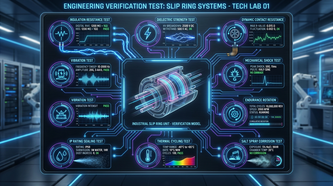
Dielectric Strength (Hi-Pot Test): Applying test voltages (typically 1,000V to 1,500V AC at 50/60 Hz for 60 seconds) between independent circuits and between circuits and ground enclosure to verify insulation integrity.
Insulation Resistance: Measuring high-voltage insulation resistance using a megohmmeter (typically ≥ 500 MΩ at 500 VDC).
Static & Dynamic Contact Resistance: Measuring resistance variations under static conditions and continuously during 360-degree rotation. Dynamic contact resistance variation must stay within strict milliohm limits (e.g., < 10 mΩ) to ensure stable signal transmission.
Signal Testing
Data Transmission Stability: Bit Error Rate (BER) testing for industrial Ethernet and bus protocols.
Packet Loss & Eye Diagram Verification: Measuring signal attenuation, jitter, and signal-to-noise ratio (SNR) under continuous rated rotational speed.
Mechanical Testing
Rotational Endurance Testing: Accelerated life testing under rated load, speed, and vibration profiles to verify brush wear rates and bearing longevity.
Torque Monitoring: Measuring starting torque and continuous rotational torque consistency.
Environmental Testing
IP Ingress Verification: Pressure testing and submersion testing according to IEC 60529.
Thermal & Humidity Cycling: Environmental chamber testing (-40°C to +85°C at 95% RH) to verify housing seal integrity and thermal expansion stability.
Salt Spray Corrosion Testing: ASTM B117 salt fog exposure testing for marine-bound housing configurations.
CE, RoHS, and Application-Specific Requirements
Material & Environmental Compliance: Verify materials comply with RoHS (Restriction of Hazardous Substances) and REACH directives.
Regulatory Declarations: Distinguish clearly between material self-declarations, CE marking, and specialized third-party equipment certifications (e.g., UL, CSA, ATEX). OEM buyers should confirm exact certification requirements during RFQ alignment rather than assuming blanket compliance across all catalog models. Engineering selection parameters can be cross-referenced with the Jinpat Industrial Slip Ring Technology Guide.
Standard vs Custom Slip Rings
OEM engineering teams must balance component standardization against performance customization when integrating rotary joints.
When a Standard Slip Ring Is Enough
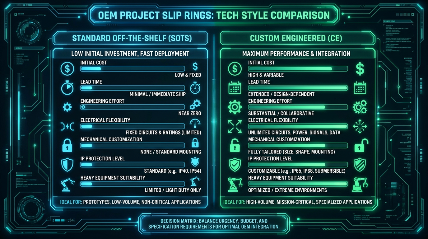
Standard off-the-shelf slip rings are cost-effective and suitable when application demands align with standard catalog configurations:
Standard circuit counts (e.g., 6, 12, 18, 24 rings).
Moderate electrical current (signal to 10A per ring) and standard voltages (240V/380V AC).
Standard installation dimensions with ample axial and radial envelope clearance.
Normal indoor industrial operating environments with standard IP54 sealing.
Short project development timelines requiring off-the-shelf prototype delivery.
When a Custom Slip Ring Is Necessary
Custom-engineered slip rings are required when equipment operating parameters exceed standard product envelopes:
High continuous electrical current (> 50A to 1,500A+) or high voltage (> 1,000V AC).
Multi-protocol hybrid integration (combining power, Ethernet, CAN Bus, fiber optics, and fluid channels).
Restricted or unusual installation space envelopes requiring custom hollow-bore apertures or non-standard mounting flanges.
Extreme environmental protection requirements (IP67, IP68, IP69K, or explosion-proof ATEX ratings).
Severe vibration, shock, or marine salt-spray corrosive environments.
Specialized connector harnessing, pre-wired flying lead specifications, or integrated rotary encoder mounts.
Cost, Lead Time, and Performance Trade-Offs
Standard Products: Deliver lower initial unit purchasing costs, zero non-recurring engineering (NRE) fees, and immediate off-the-shelf availability. However, standard models may force mechanical compromises, require external adapter plates, or present higher failure risks in demanding environments.
Custom Engineering: Incurs upfront NRE charges and longer initial prototype lead times, but provides flawless mechanical integration, optimal electrical performance, reduced overall equipment assembly labor, and maximum long-term machine reliability.
Lifecycle Cost, Maintenance, and Reliability
Purchasing decisions based solely on initial component cost frequently result in severe financial losses due to unplanned field downtime, premature replacement labor, and warranty claims.
Maintenance Requirements
Inspection Intervals: Routine visual inspection of housing seals, cable glands, and mounting torque.
Brush Wear & Contact Surface Inspection: Monitoring brush material wear on high-duty silver-graphite or carbon systems.
Cleaning Requirements: Periodic removal of accumulated conductive brush dust in open or serviceable industrial slip rings.
Maintenance-Free Designs: Units utilizing gold-on-gold wire brush technology operate completely sealed and maintenance-free throughout their operational life.
Common Failure Modes
Understanding failure mechanisms enables proactive engineering preventive measures:
Excessive Brush Wear: Caused by overspeed, excessive current density, high surface roughness, or abrasive dust ingress.
Increased Contact Resistance & Noise: Caused by surface oxidation, brush contamination, or insufficient contact spring force.
Signal Instability & Data Loss: Caused by poor shielding, impedance mismatches, or high dynamic contact noise under vibration.
Overheating & Insulation Breakdown: Caused by electrical overloads, insufficient thermal dissipation, or environmental moisture ingress.
Water/Dust Ingress: Caused by degraded housing O-rings, damaged cable glands, or incorrect IP selection.
Spare Parts and Replacement Planning
Critical Spares: For high-uptime industrial machinery (e.g., port cranes, mining rigs), OEM buyers should maintain complete replacement slip ring assemblies in regional spare parts depots.
Component Compatibility: Ensure the supplier guarantees long-term form-fit-function component interchangeability across multi-year OEM production runs.
Lead Time and Downtime Risk
Production Continuity: Evaluate supplier manufacturing lead times for both standard production runs and emergency replacement units. Unplanned machinery downtime in heavy construction or offshore operations can incur financial losses exceeding tens of thousands of dollars per day.
Total Cost of Ownership
Total Cost of Ownership (TCO) is calculated by evaluating the full lifecycle expenditure:
TCO = Initial Purchase Price + Engineering Integration Cost + Maintenance Labor + Downtime Risk + Replacement Expense
Investing in a high-reliability, custom-engineered slip ring upfront minimizes maintenance overhead, eliminates field retrofits, and protects the OEM's brand reputation.
How to Evaluate a Slip Ring Supplier
Evaluating a slip ring supplier requires auditing their engineering design capabilities, manufacturing quality controls, testing infrastructure, and long-term technical support.
Engineering Capability
Application Comprehension: Ability of supplier application engineers to analyze complex electromechanical requirements, structural tolerances, and thermal constraints.
Multi-Disciplinary Design: In-house expertise across electrical engineering, mechanical CAD modeling, finite element analysis (FEA), high-speed data transmission, electro-optics, and fluid dynamics.
Customization Experience: Proven track record of developing custom rotary solutions rather than forcing catalog standard products.
Application Experience
Industry Track Record: Verify supplier experience in your specific equipment sector (e.g., excavators, offshore winches, robotic automation, or medical machinery).
Risk Identification: Demonstrated ability to identify potential design risks (e.g., resonance vibration, thermal expansion interference, signal crosstalk) during initial drawing reviews.
Testing Capability
In-House Testing Facilities: Verify availability of high-voltage dielectric testers, insulation meters, dynamic contact resistance test rigs, bit-error-rate data analyzers, multi-axis vibration tables, IP water test chambers, thermal shock chambers, and salt spray test cabinets.
Test Certification: Ability to provide certified factory acceptance test (FAT) reports with every production serial number.
Quality Control
Quality System Certifications: ISO 9001 quality management system certification.
Incoming & In-Process Inspection: Stringent raw material inspection (brush wire metallurgy, ring gold-plating thickness), clean-room assembly for sensitive signal rings, and comprehensive final electrical testing.
Traceability: Complete serial-number component traceability from raw materials to final shipment.
Certifications and Compliance Support
Documentation Packages: Provision of 3D STEP models, detailed 2D engineering drawings, material compliance certificates (RoHS/REACH), and test declarations.
Lead Time and Production Capability
Rapid Prototyping: Fast engineering turnarounds for prototype evaluation (typically 2 to 4 weeks).
Scalable Batch Manufacturing: Production infrastructure capable of supporting flexible batch orders from low-volume specialized machinery to high-volume annual OEM frame contracts.
Spare Parts and After-Sales Support
Lifecycle Support: Long-term technical support, spare parts availability, drawing configuration management, and field engineering assistance.
Industry and Rotary Transmission Experience
When selecting a rotary transmission partner, OEMs should evaluate suppliers with extensive, proven multi-media engineering capabilities. For example, OEM engineering teams evaluating demanding rotary power, signal, fiber optic, and fluid transmission challenges can evaluate JINPAT custom slip ring solutions as a reference for nearly three decades of specialized rotary engineering, rigorous factory testing, and tailored OEM application expertise across global heavy machinery markets.
RFQ Checklist: What Information Should You Prepare Before Ordering?
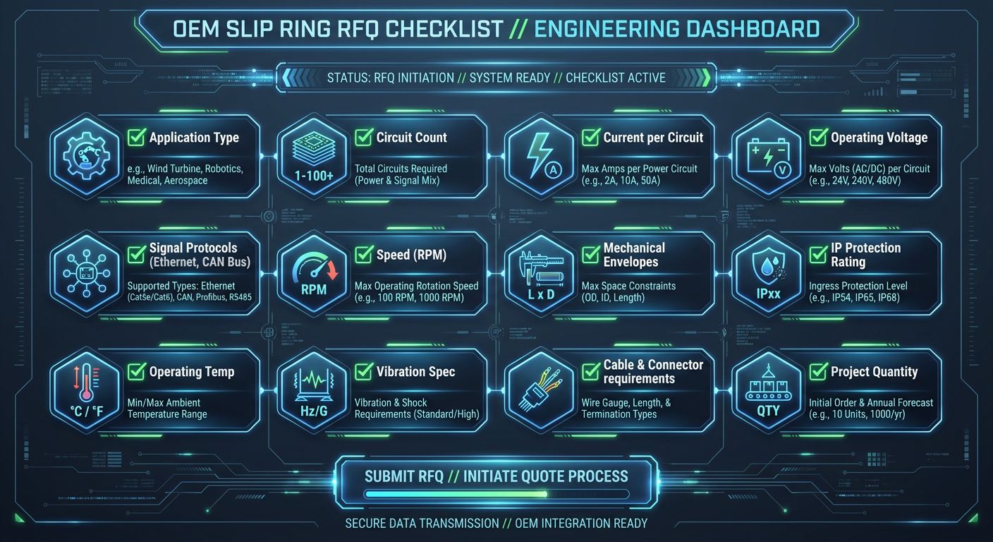
Providing complete technical details during the initial Request for Quotation (RFQ) stage dramatically reduces engineering clarification cycles, ensures accurate pricing, and prevents costly design revisions.
Application Information
Machine / equipment type (e.g., 30-ton crawler excavator, port container crane, packaging carousel).
Rotating system function and operating context.
Installation location (indoor sheltered, outdoor exposed, marine deck, underground mining).
Target project phase (new platform design, existing machine upgrade, direct replacement).
Electrical Requirements
Number of power circuits and signal circuits.
Continuous current rating per circuit (Amperes).
Operating voltage per circuit (Volts AC/DC).
Maximum surge, peak transient, or motor startup current.
Grounding and neutral line requirements.
Signal and Communication Requirements
Data bus protocols (Ethernet 100M/1G, CAN Bus, Profibus, RS-485).
Analog signal types (4-20mA, 0-10V, thermocouple, RTD).
Encoder / feedback signal types.
Fiber optic requirements (single-mode/multi-mode, optical wavelength, channel count, connector type).
Shielding and isolation requirements.
Mechanical Requirements
Maximum outer diameter (OD) and maximum overall axial length limits.
Through-hole bore requirement (internal diameter size in mm).
Mounting interface (flange mounting, shaft mounting, torque arm pin).
Rotational speed: continuous operating RPM and maximum overspeed RPM.
Rotation direction (single direction, bi-directional, oscillating angle).
Duty cycle profile (24/7 continuous, intermittent, index start-stop).
Environmental Requirements
Operating ambient temperature range (minimum °C to maximum °C).
Required IP protection level (IP54, IP65, IP67, IP68, IP69K).
Exposure factors: dust, rain, washdown chemicals, continuous humidity.
Marine salt spray exposure requirements.
Mechanical shock and structural vibration levels (G-force / frequency profile).
Hazardous area explosion-proof certifications (ATEX / IECEx zone and temp class).
Cable and Connector Requirements
Flying lead wire length (stator side length and rotor side length in mm).
Wire type and insulation requirements (Teflon, PVC, PUR jacket).
Exit orientation (axial exit, radial exit, right-angle gland).
Specified connector part numbers (e.g., Deutsch, Amphenol, M12 industrial Ethernet, flying leads).
Cable protection conduit or corrugated hose fittings.
Project Information
Prototype sample quantity and required prototype delivery date.
Estimated annual OEM volume and target production batch sizes.
Existing 2D engineering drawings, 3D CAD models, or photographs of existing installation space.
Common Slip Ring Buying Mistakes to Avoid
Choosing Based on Price Alone
Selecting a slip ring based solely on the lowest initial purchase price frequently leads to high total costs. Low-cost units often utilize inferior contact plating, lower-grade bearings, and improper seals, leading to premature brush wear, signal noise, water ingress, and catastrophic machine downtime.
Failing to Specify Current Per Circuit
Specifying only the total aggregate current (e.g., "100 Amps total") without detailing individual circuit current ratings prevents proper conductor sizing. A slip ring carrying one 80A line and twenty 1A signal lines requires fundamentally different internal ring geometry than one carrying ten 10A lines.
Ignoring Signal Integrity
Routing high-speed digital communications (such as CAN Bus or Ethernet) through unshielded, non-impedance-matched signal tracks causes severe data packet drops and electrical interference from adjacent power channels.
Underestimating Environmental Conditions
Failing to account for real-world environmental exposure—such as ambient temperature extremes, high-pressure washdowns, fine silica dust, or salt spray—leads to rapid seal degradation, housing corrosion, and electrical short circuits.
Ignoring Installation Constraints
A technically perfect slip ring is useless if it cannot be installed. Failing to verify outer diameter limits, axial length clearances, cable exit bend radii, or rigidly clamping both rotor and stator without a flexible torque arm results in mechanical binding and bearing failure.
Over-Specifying Requirements
Requesting unnecessary high IP ratings (e.g., IP68 submersion sealing for an indoor machine), excess spare circuits, or overly conservative current safety factors increases physical size, weight, unit cost, and manufacturing lead time.
Failing to Plan for Maintenance and Spare Parts
Ignoring long-term component availability and replacement logistics during initial machine design creates critical single-point supply chain risks during post-sale field service.
Providing Incomplete RFQ Information
Submitting incomplete specifications to suppliers results in prolonged engineering clarification cycles, inaccurate cost estimates, and risk of receiving mis-matched prototype units.
Final Slip Ring Buying Checklist
Before releasing your final technical specification or issuing an RFQ to slip ring suppliers, confirm that every parameter below has been fully documented:
Equipment application type and operational context defined.
Required structural slip ring type selected (through-bore, flange, pancake, capsule, high-current, or hybrid).
Total electrical circuit count finalized (power circuits, signal circuits, bus channels, spares).
Individual circuit continuous and peak current specified.
Operating voltage specified for power and signal channels.
Data bus, communication protocols, and fiber optic requirements defined.
Normal operating RPM and maximum overspeed RPM specified.
Duty cycle and rotational motion profile defined.
Maximum allowable outer diameter, axial length, and through-bore size confirmed.
Rotor and stator mounting interfaces and flexible torque arm method defined.
IP protection rating (IP54 to IP69K) specified based on exposure.
Ambient operating temperature range (-40°C to +85°C) specified.
Shock, vibration, and marine salt spray exposure defined.
Cable types, wire lengths, exit direction, and connector part numbers specified.
Applicable compliance standards (CE, RoHS, ATEX/IECEx) confirmed.
Target operational service life (revolutions / service hours) defined.
Prototype quantity, annual production volume, and target delivery schedule set.
Installation envelope drawings, 3D STEP models, or photos attached to RFQ.
Conclusion: From Specification to Supplier Selection
Selecting the ideal slip ring assembly requires a structured engineering approach that aligns electrical requirements, signal integrity, mechanical packaging, environmental sealing, testing verification, and supplier capabilities.
Rather than attempting to force a standard catalog part into a demanding OEM machinery platform, engineering teams achieve the highest long-term reliability by defining clear application parameters upfront. A complete, well-prepared RFQ eliminates guesswork, speeds up technical evaluation, and ensures the delivered rotary joint performs reliably over millions of rotational cycles.
When your application involves high continuous current, complex signal bus protocols, extreme outdoor environments, or severe mechanical space constraints, engaging early with an experienced rotary transmission engineering team ensures optimal design integration and long-term machinery performance.
Need Technical Assistance with Your Slip Ring Design?
If you are developing a new OEM machinery platform or upgrading an existing rotary assembly, contact JINPAT's rotary transmission engineering team for a complimentary technical specification review, 3D CAD envelope analysis, and customized quotation tailored to your operational requirements.